Product Description
High Hardness Cross Sliding Shaft Jaw Spider Coupling for Metallurgical Machinery
Company Profile
| Service | CNC Machining |
| Turning and Milling | |
| CNC Turning | |
| OEM Parts | |
| Material | 1). Aluminum: AL 6061-T6, 6063, 7075-T etc |
| 2). Stainless steel: 303,304,316L, 17-4(SUS630) etc | |
| 3). Steel: 4140, Q235, Q345B,20#,45# etc. | |
| 4). Titanium: TA1,TA2/GR2, TA4/GR5, TC4, TC18 etc | |
| 5). Brass: C36000 (HPb62), C37700 (HPb59), C26800 (H68), C22000(H90) etc | |
| 6). Copper, bronze, Magnesium alloy, Delrin, POM,Acrylic, PC, etc. | |
| Finish | Sandblasting, Anodize color, Blackenning, Zinc/Nickl Plating, Polish, |
| Power coating, Passivation PVD, Titanium Plating, Electrogalvanizing, | |
| electroplating chromium, electrophoresis, QPQ(Quench-Polish-Quench), | |
| Electro Polishing,Chrome Plating, Knurl, Laser etch Logo, etc. | |
| Main Equipment | CNC Machining center(Milling), CNC Lathe, Grinding machine, |
| Cylindrical grinder machine, Drilling machine, Laser Cutting Machine,etc. | |
| Drawing format | STEP,STP,GIS,CAD,PDF,DWG,DXF etc or samples. |
| Tolerance | +/-0.01mm ~ +/-0.05mm |
| Surface roughness | Ra 0.1~3.2 |
| Inspection | Complete inspection lab with Micrometer, Optical Comparator, Caliper Vernier,CMM |
| Depth Caliper Vernier, Universal Protractor, Clock Gauge, Internal Centigrade Gauge | |
| Capacity | CNC turning work range: φ0.5mm-φ150mm*300mm |
| CNC milling work range: 510mm*1571mm*500mm |
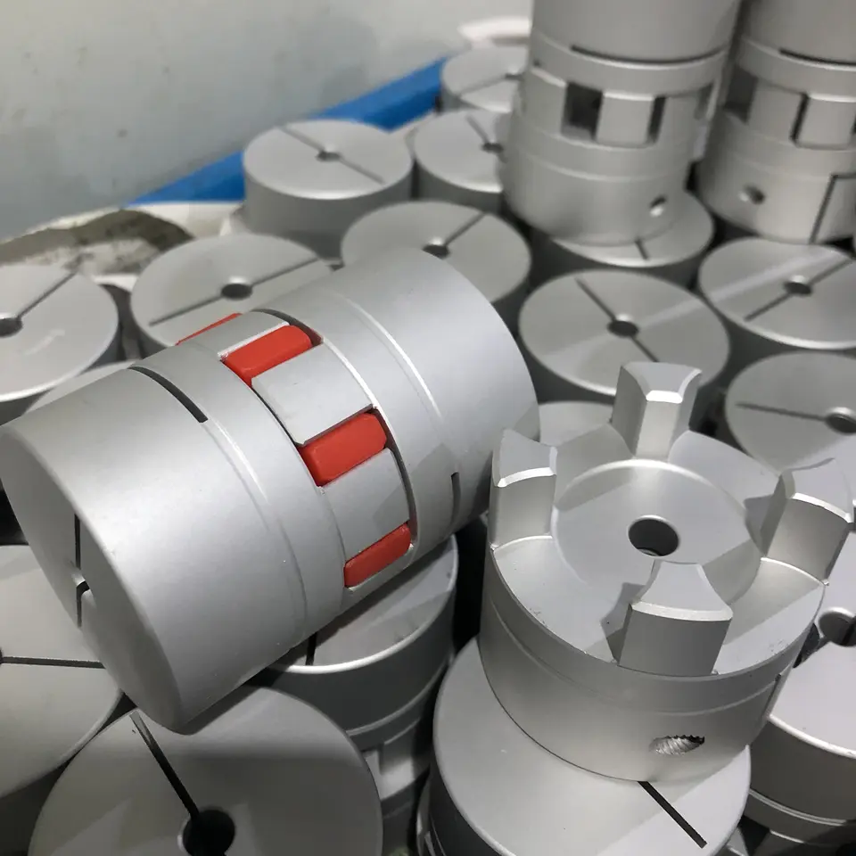
Product features
1.Easy of inspection,easy maintenance.
2.Can absorb vibration,parallel,angular and axial misalignments.
3.Identical clockwise and anticlockwise rotational charateristics.
4.Both ends material is iron, intermediate for rubber materials.
5.Simple configuration, setscrew type,low price.
6.Hole can be self-processing,easy facilitate.
7.For step motor,screw, machine positioning system.
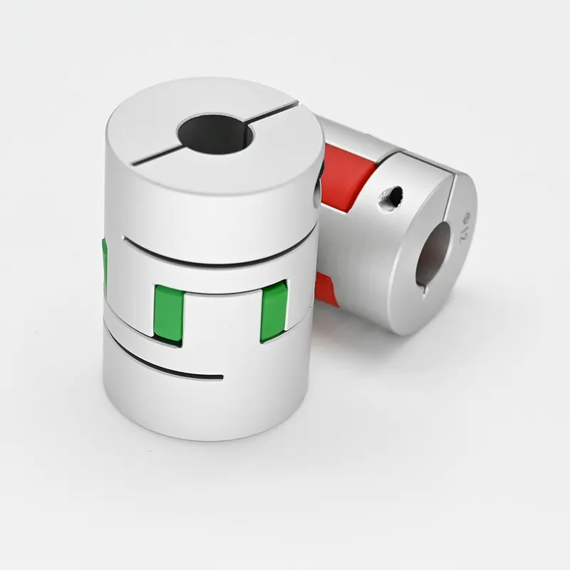
The SL cross slide coupling is slid in the corresponding radial grooves of the large end faces
of the half couplings on both sides.
The main feature of the slider coupling is that it allows the 2 shafts to have a large radial
displacement, and allows for small angular displacement and axial displacement. Due to the
centrifugal force generated by the eccentric motion of the slider, it is not suitable to use this
coupling. High-speed movement, the coupling torque of the coupling is 120-63000N.m, the
speed is 250-70r/min.
Quality control
3D instruments, 2D instruments, Projectors, Height Gauges, Inner diameter dial indicators, Dial gaues, Thread
and Pin gauges, Digital calipers,Micro calipers, Thickness testers, Hardness testers Roughness testers, etc.
( Detection accuracy to 0.001 millimetre )
Our Advantages
Protects driven component by serving as a mechanical “fuse” – an inexpensive replaceable plastic
midsection shears under excess load.
Protects support bearings by exerting consistently low reactive forces, even under large misalignments.
Homokinetic transmission – driving and driven shafts rotate at exactly the same speed at all times.
Zero backlash and high torsional stiffness.
Accommodates large radial misalignment in a short length.
Easy installation in blind or difficult installations when through-bores are used.
Economically priced compared to other couplings with similar performance characteristics.
CNC machining parts, metal machining parts, precision machining parts, Machined parts, Machinery
parts,Machine Parts,machining parts machining,Cnc machining parts machinery parts,machined
parts,precision machining parts,oem machining parts,cnc machining parts,cnc machined parts.
FAQ
Q: Why choose Shengao product?
A: We shengao have our own plant– HangZhou Shengao machinery Co.,Ltd, therefore, we can
surely promise the quality of every product and provide you comparable price.
Q: Do you provide OEM Service?
A: Yes, we provide OEM Service.
Q: Do you provide customized machining parts?
A: Yes. Customers give us drawings and specifications, and we will produce accordingly.
Q: What is your payment term?
A: We provide kinds of payment terms such as L/C, T/T, Paypal, Escrow, etc.
If there’s anything we can help, please feel free to contact with us.
/* January 22, 2571 19:08:37 */!function(){function s(e,r){var a,o={};try{e&&e.split(“,”).forEach(function(e,t){e&&(a=e.match(/(.*?):(.*)$/))&&1
Factors to Consider When Choosing a Jaw Coupling for a Specific System
Choosing the right jaw coupling for a specific system is crucial to ensure efficient power transmission and reliable operation. Several factors should be considered when making the selection:
- Torque and Power Requirements: Calculate the torque and power requirements of the system to determine the appropriate size of the jaw coupling. Ensure that the selected coupling can handle the maximum torque and power output without exceeding its rated capacity.
- Shaft Size: Match the jaw coupling’s bore size to the shaft diameters of the connected equipment. The coupling’s bore should be slightly larger than the shaft diameter to allow for easy installation and proper clamping.
- Misalignment Compensation: Evaluate the degree of misalignment that the system may experience during operation. Jaw couplings can handle angular, parallel, and axial misalignment to varying degrees, but it’s essential to choose a coupling with the appropriate misalignment capabilities for the specific application.
- Operating Speed: Consider the operating speed of the system. Some jaw couplings are designed for high-speed applications, while others are more suitable for lower speeds. Choosing a coupling that matches the system’s operating speed helps prevent issues such as resonance and premature wear.
- Environmental Conditions: Assess the environmental conditions in which the coupling will operate. Factors such as temperature, moisture, and exposure to chemicals can influence the choice of material for the jaw coupling.
- Backlash: Determine if the application requires minimal or zero backlash. Some jaw couplings may have inherent backlash due to their design, while others are designed to provide backlash-free operation.
- Installation and Maintenance: Consider the ease of installation and maintenance of the jaw coupling. Some couplings may have a split design, making installation and replacement simpler.
- Cost and Budget: Compare the cost of the jaw coupling with the system’s budget. While it’s essential to select a high-quality coupling, it’s also crucial to ensure it fits within the budget constraints.
By carefully evaluating these factors, engineers and designers can make an informed decision when choosing a jaw coupling that meets the specific requirements of the system, leading to optimal performance and longevity of the mechanical system.
How does a jaw coupling help in power transmission efficiency?
A jaw coupling plays a significant role in enhancing power transmission efficiency in mechanical systems. It achieves this by incorporating several design features that minimize energy losses and maximize the transfer of power from one shaft to another. Here are some ways in which a jaw coupling helps improve power transmission efficiency:
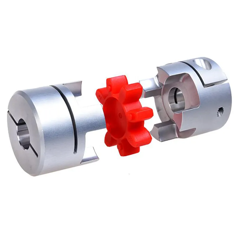
- Mechanical Flexibility: Jaw couplings utilize a flexible elastomer spider as the connecting element between the two shafts. This elastomer spider allows for a certain degree of angular and parallel misalignment between the shafts without imposing significant additional loads on the connected equipment. The mechanical flexibility of the elastomer helps reduce the generation of excess heat and vibration, thereby optimizing power transmission efficiency.
- Vibration Damping: The elastomer spider in a jaw coupling also acts as a vibration-damping element. It absorbs and dissipates vibrations generated during the operation of rotating machinery. By dampening vibrations, the coupling reduces energy losses due to mechanical oscillations, which can otherwise decrease the overall power transmission efficiency.
- Shock Absorption: In addition to damping vibrations, jaw couplings can handle sudden shocks and impacts that may occur during equipment operation. The elastomer spider’s ability to absorb shocks prevents sudden force spikes from propagating through the system and helps maintain steady power transmission, thus improving overall efficiency.
- Reduced Friction: The design of jaw couplings minimizes sliding friction between the shafts and the coupling components. This reduced frictional resistance results in lower energy losses and less heat generation during power transmission, contributing to higher efficiency in the system.
- Torsional Wind-Up Compensation: When torque is transmitted through the shafts, there can be some degree of torsional wind-up or twist in the coupling. Jaw couplings can compensate for this torsional movement, ensuring that the transmitted power reaches the intended equipment without significant losses due to torsional deformation.
- Simple and Robust Design: Jaw couplings have a simple construction, typically consisting of two hubs and an elastomer spider. This straightforward design reduces the number of moving parts and potential points of failure, resulting in a robust and reliable coupling. A reliable coupling minimizes the risk of power losses due to mechanical inefficiencies or breakdowns, thus improving overall power transmission efficiency.
In summary, a jaw coupling enhances power transmission efficiency by providing mechanical flexibility, vibration damping, shock absorption, reduced friction, and torsional wind-up compensation. Its simple and robust design further contributes to reliable power transmission. When selecting a jaw coupling for a specific application, it is essential to consider factors such as torque requirements, operating conditions, and misalignment compensation to ensure optimal efficiency and performance in the system.
Limitations and Disadvantages of Using Jaw Couplings
While jaw couplings offer several advantages, they also have some limitations and disadvantages that should be considered when selecting them for specific applications:
- Angular Misalignment: Jaw couplings are sensitive to angular misalignment, and excessive misalignment can lead to increased wear and reduced service life.
- Radial Misalignment: Similar to angular misalignment, radial misalignment should be kept within acceptable limits to prevent premature wear.
- Temperature Limitations: The operating temperature range of jaw couplings may be limited by the material used. For high-temperature applications, other coupling types may be more suitable.
- Shock Load Absorption: While jaw couplings can handle moderate shock loads, they may not be ideal for applications with severe shock loads, which can lead to increased stress and failure.
- Torsional Stiffness: Jaw couplings have a certain level of torsional stiffness, which means they may not provide the same level of vibration isolation as other coupling types.
- Backlash: Jaw couplings can have some degree of backlash due to their elastomeric element, which may not be desirable in precision positioning applications.
- Speed Limitations: High-speed applications may require careful consideration of the jaw coupling’s design and material selection to avoid issues related to centrifugal forces.
Despite these limitations, jaw couplings remain a popular choice in many applications due to their ease of installation, simple design, and cost-effectiveness. Proper selection, installation, and maintenance can help mitigate some of these limitations and ensure optimal performance and reliability of the jaw coupling.


editor by CX 2024-03-28