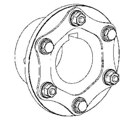
The following is often a sample application made use of to illustrate the regular method for choosing a Disc coupling. 
Sample Application:
An organization includes a compressor application applying a 225 horsepower electrical motor working at one,150 RPM to drive a three cylinder multi stage reciprocating air compressor. The electrical motor features a 3-3/8 inch shaft which has a 7/8 inch keyway plus the compressor includes a 92mm shaft by using a 25mm keyway. The shaft separation is roughly seven inches in between shaft ends with some capability to change the motor area. The shafts have a parallel misalignment/offset of approximately 1/32 of an inch.
Phase one: The first phase should be to establish what coupling variety is to be selected for this application. Because the SU Type coupling only supports
a single flex plane, it can only accommodate angular and axial misalignment, but not parallel misalignment. The following preference would be to seem at an SX or DI Form coupling. The six bolt SX Type will accommodate the two parallel misalignment as well as the defined shaft separation. The size will probably be determined from the variety torque as well as shaft diameters.
Phase 2: Subsequent, determine the application torque and apply the service issue to calculate the variety torque.The formula used to calculate torque is as follows:
Application Torque ( in¡§Clb ) = ( HP x 63025 )/RPM
or Nm = ( KW x 9550)/RPM
Plugging while in the numbers through the application description:
Application Torque ( in-lbs ) =(HP x 63025)/RPM = (225 x 63025)/1150 = twelve,331 in-lbs
Application Torque x Service Factor = Selection Torque
12,331 in-lbs x 3.0 = 36,993 in-lbs
Phase three: Utilize the SX coupling tables and note that the SX 202-6 is rated at forty,700 in-lbs, a lot more than enough to handle the selection torque calculated in phase 2. The SX202-6, however, won’t support the 92mm shaft size. The next bigger size coupling, the SX228-6, will support the 92mm shaft size along with the shaft separation dimension (BSE) is 6.88 inches, very near to the application?¡¥s wanted 7 inch separation. The SX228-6 is rated at 62,000 in-lbs which may possibly appear to be excessive, on the other hand, the coupling size is important to take care of the bore size.
Step 4: The SX228-6 coupling is rated for a optimum unbalanced speed of three,400 RPM, more than adequate to help the application velocity of one,150 RPM.
Phase 5: To find out if your coupling will take care of the parallel misalignment, use the trig perform of tan 1?? = offset permitted for one inch = 0.0174
Multiply the 0.0174 x the distance in between disc packs or ??S?¡¥ dimension from your table on webpage D-13, or five.50 inches.
The allowable parallel offset is 0.0174 x five.50 = 0.096 inches. The maximum offset for your application is 1/32 inches (0.031), as a result this coupling can accommodate the parallel misalignment.
Note: It really is often suggested to try to install the coupling at approximately 20% of the allowable misalignment. For this coupling the installer should make an effort to accomplish far better than 0.020 parallel misalignment in the time of set up. This will make it possible for to the extra misalignment which will arise as the outcome of tools settle and standard equipment put on.
Measures In Picking out A Disc Coupling
Tags: